Following on from part one, which provided the theoretical knowledge for this objective as outlined in the study guide, in this post I will go over the performance-based elements. This is where we will start to get hands-on and do some configuration; as a result, this will be a bit of a long post.
Introduction to Gaia
First of all, a 10,000-foot overview of Gaia. This is the operating system - derived from Red Hat Enterprise Linux - on which every Check Point appliance and open server runs, and comes with a rich range of features including IPv4/IPv6 integration, load sharing, high availability, dynamic routing (e.g. RIP, OSPF, BGP) and multicast (IGMP and PIM), and more. Gaia can be configured and managed in one of two ways: using WebUI, the browser-based frontend, or the command-line interface (CLI) - both of which I will cover in this post.
At this point, I’m going to assume that you already have your lab up and running and are ready to get started; if not, it would be a good idea to go back to my very first post and refer to one of the resources that I’ve linked to under the Lab Topology section.
WebUI
Open up your preferred browser and navigate to the IP address of your gateway (in my case, 192.168.1.252); you can also do this on the SMS. Once you’ve signed in, you’ll be greeted with the System Overview page:
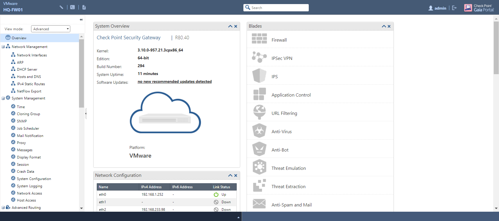
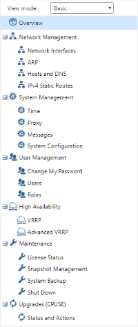
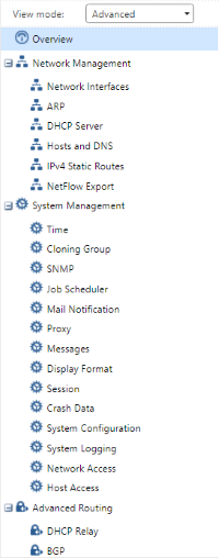
As the name suggests, this page provides a generic overview of various system parameters such as uptime, Gaia kernel and build versions, available software updates, network interface settings, software blades - enabled or otherwise - interface throughput in kb/s and packet rate (the latter two for gateways only) via individual widgets. Along the left-hand side of the page is a navigation pane that lists each WebUI page categorically. The drop-down menu at the top provides two modes of viewing the list: Basic - which shows a selected handful of pages - and Advanced, in which every page is displayed:
| Basic | Advanced |
|---|---|
|
|
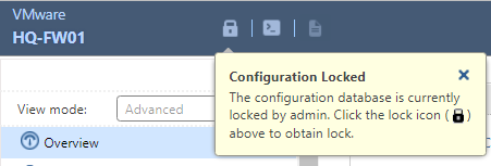
Only one user has read-write access to WebUI at any given time; all others will be provided read-only access with which to view configurations. Read-write access to WebGUI is denoted by a diagonal pencil symbol towards the top-left of the screen, as below:

When you have read-only access, this is replaced by a padlock symbol and a message explaining as such. You can click this to override the lock that’s currently held by another user, who will in turn be given read-only access:
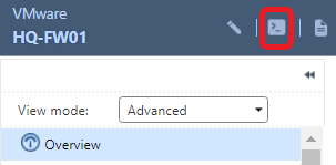
The symbol looking like a terminal prompt allows for CLI commands to be used…
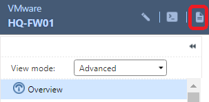
…while the button resembling a sheet of paper is used for note-taking:
You can enter any number of keywords in the search bar further to the right - this can be a configuration parameter, or anything relating to any configuration pages. Any results that relate to the keyword you have entered will be displayed:

Configuring IPv4 Settings
With an understanding of how WebUI is laid out, a good place to start configuration-wise would be to review the available network interfaces and configure these accordingly. Navigate to the Network Interfaces page, listed under Network Management:
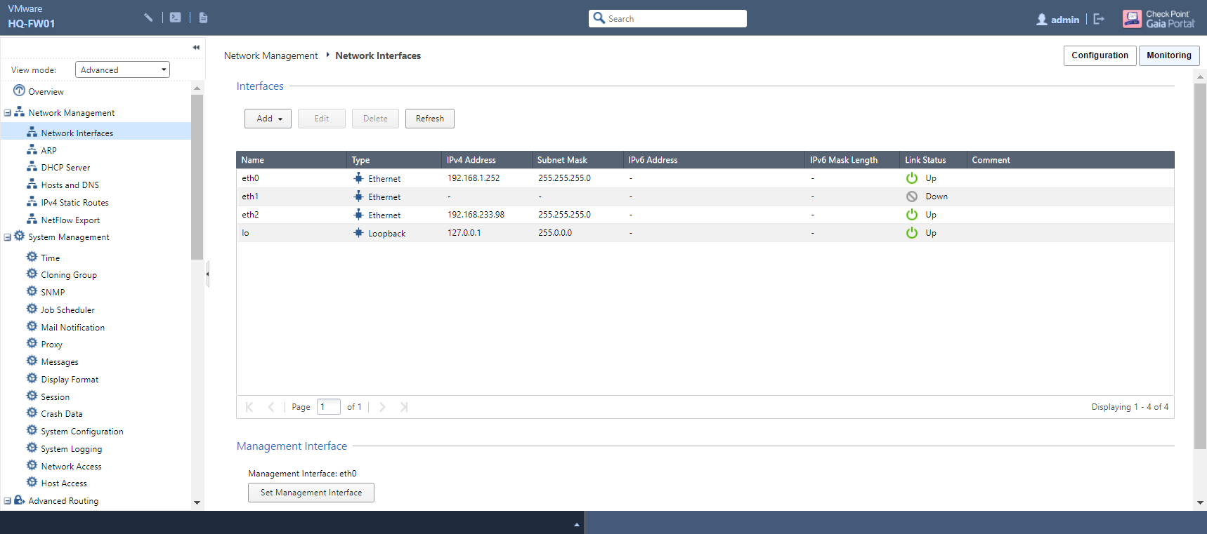
Depending on how many interfaces you allocated to your gateway when setting up the VM, you should see at least two here; in my case, three (not counting the loopback interface) are displayed. Since Eth2 is what I want to use as my Internet-facing interface, I will - for the purposes of demonstration here, as this is already up and running - select this and click the Edit button:
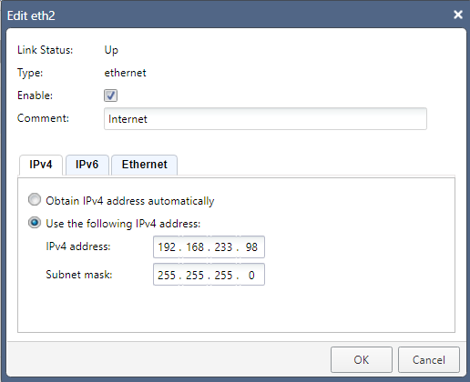
Add a comment that describes where the interface goes, enter the IPv4 address and Subnet Mask that you want to assign, and make sure to tick the Enable checkbox before clicking OK to apply the change.
Adding Static Routes
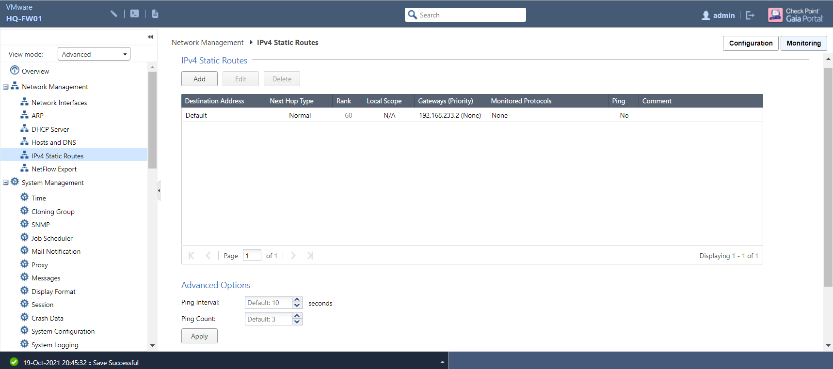
Now that the IP addresses have been set up, the next logical step would be to make sure that our internal traffic has a means of communicating with the outside world. (After all, a perimeter firewall that didn’t allow Internet access would be pretty redundant to say the least.) Go to the IPv4 Static Routes page:
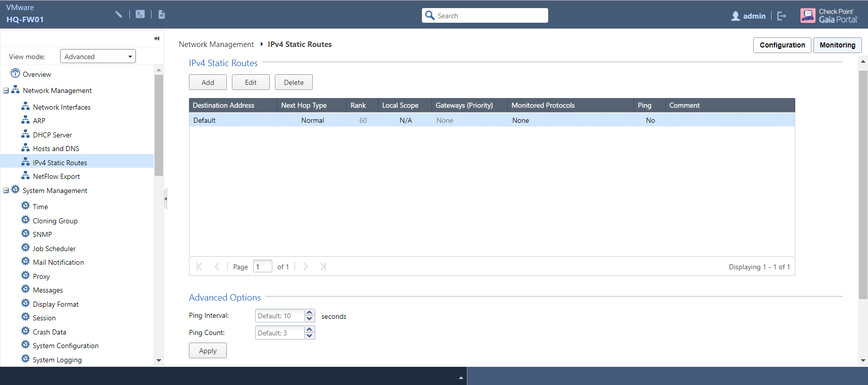
The only existing entry in the routing table is the default route (a route of last resort for when no specific routes are available for any given destination) with no exit gateway specified at present. Select the Default entry and click Edit:
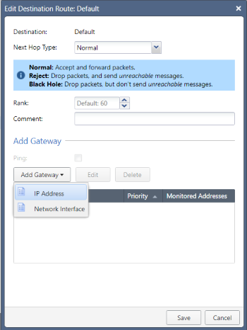
Leaving the Next Hop Type and Rank fields at their respective default values, click the Add Gateway button. You will have the option of providing a next-hop IP address or specifying the exit interface - I’ll opt for the former:
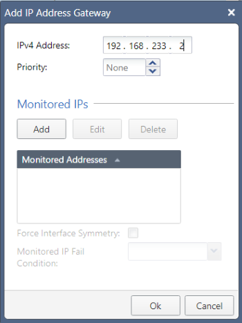
The next-hop IP address will be the default gateway for VMware Workstation’s VMnet8 network; you can confirm what your own one is by looking at the NAT Settings in the Virtual Network Editor, but it will always end in .2. Click OK to confirm, review that all is correct…
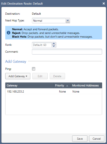
…then click Save to apply the change:
Adding New Users
Using the baked-in Admin user account as your only means of administering your Check Point estate is highly discouraged for several reasons. If multiple users are given access to it, narrowing changes down to a specific individual becomes an impossible task - not to mention the fact that there is no limit to what changes can be made.
Head to the Users page, listed under User Management:
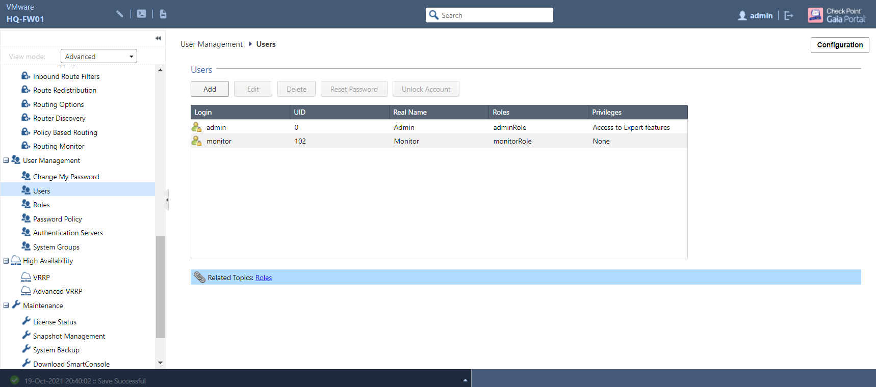
Along with the Admin user, you will also see another default user named Monitor which has read-only access to WebUI and the CLI. Like the Admin role, this cannot be amended - aside from changing the password - or deleted. To create a new user, click the Add button:
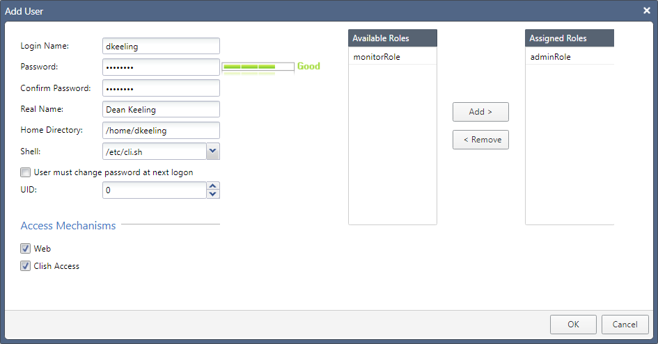
The steps are self-explanatory enough: provide a username and password, and the real name of the user. The Shell field specifies which CLI shell (Clish by default; you can also choose Bash among a handful of others, or even deny shell access outright) will be used, while forcing a password change upon first login - although not a requirement - is certainly recommended.
UID, or User ID, is another optional field. 0 gives the user full admin privileges, while values between 103 and 65,533 will designate non-admin rights - this becomes more relevant as you start creating and defining your own role-based groups. To assign a user to one or multiple role group, select your chosen group/s in the Available Roles column and click the ‘Add >’ button (or double-click on the group name/s).
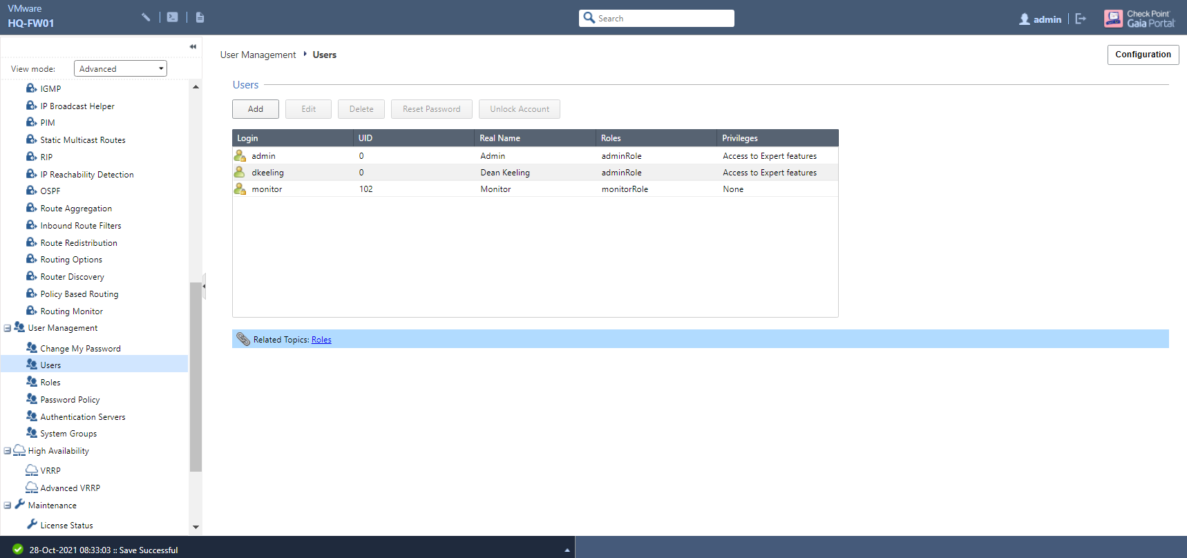
Once you’re satisfied, click OK to confirm - repeat this step as often as is required depending on how many users you require.
Creating Role Groups
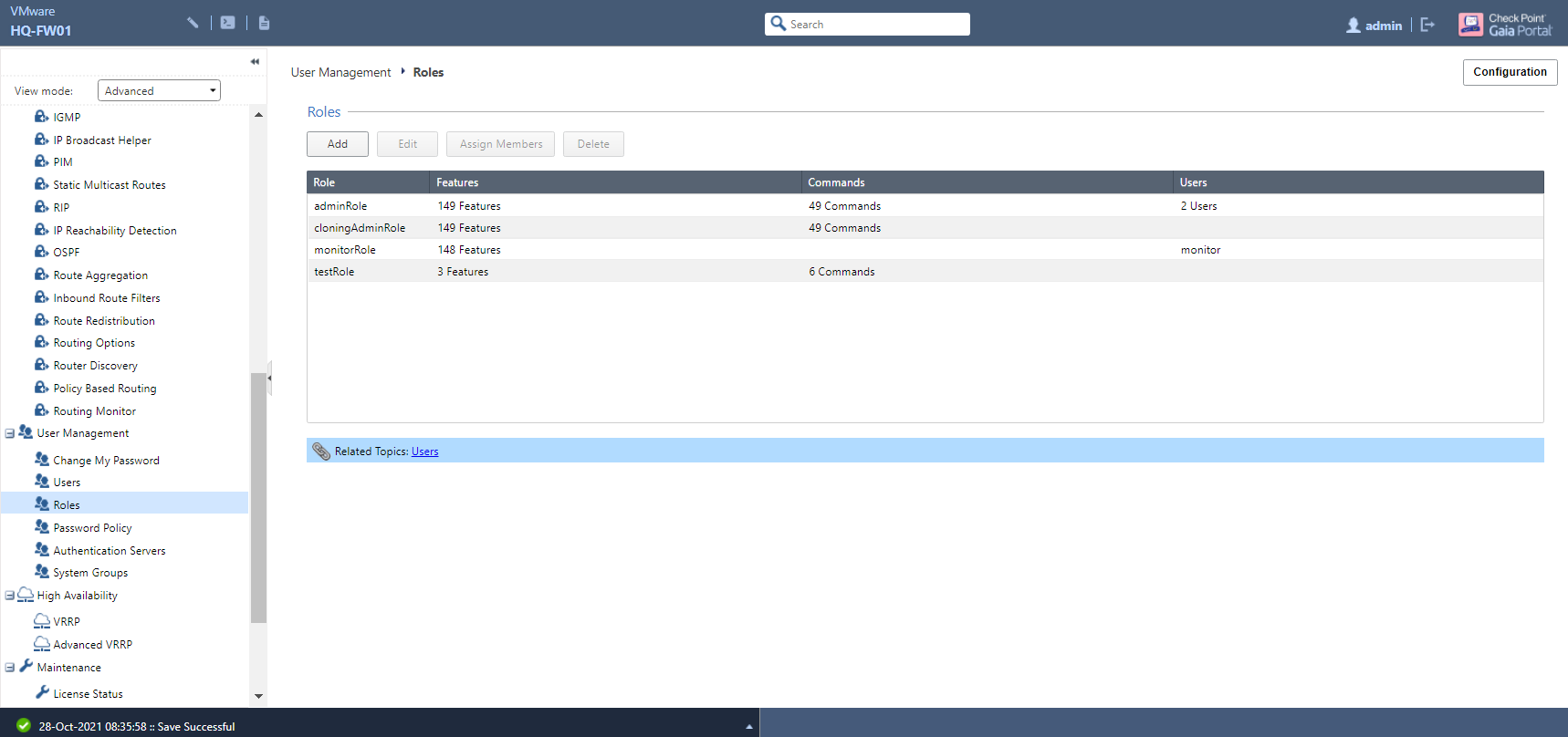
If you find the pre-configured user role groups to be too restrictive or too permissive, you can create your own and grant access to as much (or as little) WebUI functionality and CLI commands as you wish. Navigate to the Roles page:
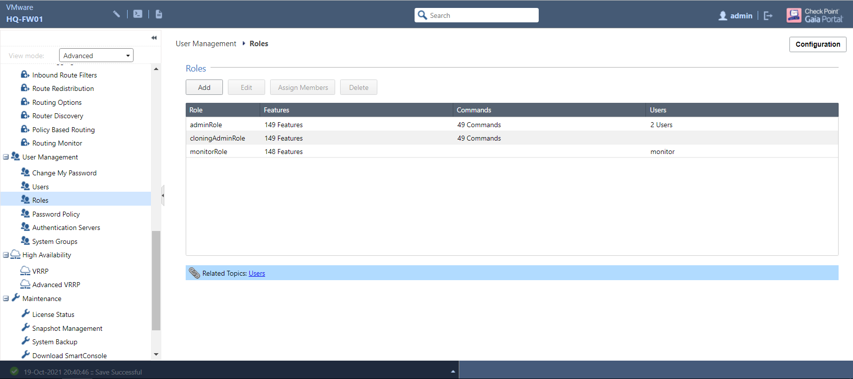
Click Add to start creating your own role group - this should ideally be given a name that clearly describes the purpose it serves and gives some indication as to what level of access is granted:
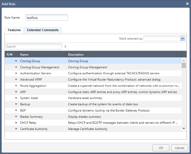
Under the Features and Extended Commands tabs, you will be shown a list of all available WebUI functions and Clish commands respectively. By default, nothing is assigned, but you can assign each individual function either Read-Only or Read/Write access - or no access - in accordance to how broad or strict you’d like your scope to be. The Gaia R80.40 admin guide provides a comprehensive list of available features and commands, as well as decriptions of what these do.
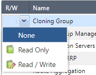
To assign access a feature at a time, click the small downward-pointing arrow and select one of the three options shown below (alternatively, you can select multiple features at once and mark them with the level of access you want):
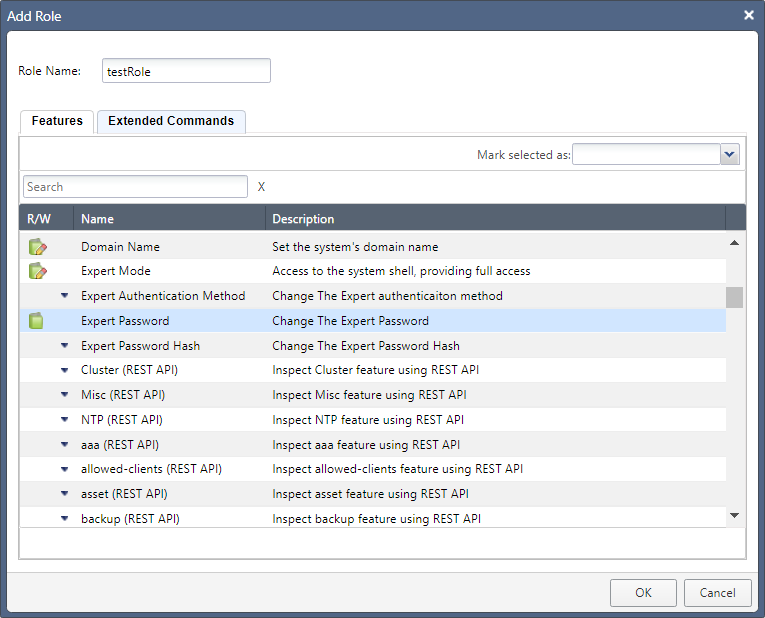
In this example, I’ve given the role Read/Write access to two features and Read-Only - denoted by the icon without the pencil - to just one:
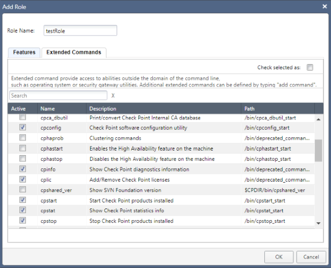
Similarly, you can do the same with Clish commands in the Extended Commands tab:
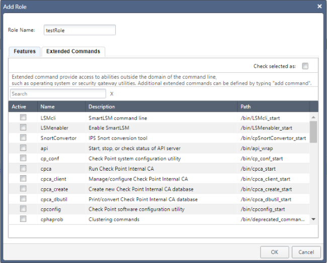
Just as was done with the features, I’ve assigned access to a small handful of commands (again, you can also select all at once and then deselect as appropriate):
When finished, click the OK button:
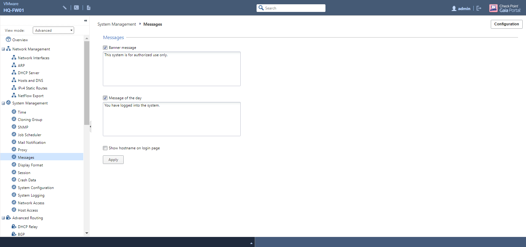
Setting System Messages
Gaia allows you to set two different types of message that are presented upon connecting remotely, often to advise that only authorised users can connect to company devices and that their activities are being monitored for legal purposes. These are the banner message, displayed just before the user enters their login credentials, and the message of the day (or just MOTD) which is presented once they have signed in:
Command-Line Interface
As mentioned earlier, the CLI is another way of configuring your gateway and SMS. Gaia uses its own shell - Clish - which is easy to use, yet restrictive; as above, it is possible to use role-based administration to limit the number of commands available to a given role group, while it also prevents the user from making potentially damaging changes at the system level (more on this later).
Clish commands use the syntax [operation] [feature] [parameters]. Let’s use the command show interfaces all as an example; this displays the settings (IPv4/v6 address information, bandwidth, status, MTU, etc…) of all network interfaces:
| Operation | Feature | Parameter |
|---|---|---|
show |
interfaces |
all |
Oftentimes, a command can also accept two - or even more - parameters and arguments:
| Operation | Feature | Parameter/s |
|---|---|---|
add |
user |
dkeeling uid 0 |
set |
interface |
eth0 link-speed 1000M/full |
Clish comes with several helpful features, a lot of which are common to almost all CLIs, if you get stuck on knowing the syntax of a particular command; one of these is tab completion. Pressing the Tab key at the prompt with no initial input will show a list of all operations (which, again, can be restricted based on role groups):
HQ-FW01>
LSMcli          - SmartLSM command line
LSMenabler      - Enable SmartLSM
SnortConvertor  - IPS Snort conversion tool
add             - Add operation.
api             - Start, stop, or check status of API server
backup          - Start a backup of the system
clear           - clear the screen
commit          - End transaction by committing changes.
config_system   - First Time Configuration tool
cp_conf         - Check Point system configuration utility
cpca            - Run Check Point Internal CA
<...output truncated...>
HQ-FW01>
If you know the first letter of the operation you want to perform but - for some reason - can’t remember the exact word, tab completion will help here too:
HQ-FW01> s
SnortConvertor - IPS Snort conversion tool
save           - Save operation.
set            - Set operation.
show           - Show operation.
sim            - SecureXL Implementation Module commands
start          - Start operation.
Once you’ve found what you’d like to do, press Space and then the Tab key again to list all available features…
HQ-FW01> show
show
aaa                - Authentication authorization and accounting
allowed-client     - Show allowed client
arp                - Display the parameters related to ARP
as                 - Show Autonomous System Number
asset              - Display hardware information
backup             - Show the status of the latest backup/restore
backup-scheduled   - Show the scheduling of backup defined in the system
backups            - List of local backups
bgp                - Show Border Gateway Protocol (BGP) configuration
bonding            - Display summary of bonding interfaces
<...output truncated...>
…and, after you’ve done that, repeat the above to show which parameters you can apply arguments to:
HQ-FW01> show configuration
aaa                  - display aaa configuration commands
aggregate            - Display Route Aggregation configuration commands
allowed-client       - Displays Allowed Clients configuration
arp                  - Display ARP configuration commands
as                   - Show Autonomous System Number configuration commands
backup-scheduled     - Display scheduled backup configuration commands
bgp                  - Display BGP configuration commands
bonding              - display bonding configuration commands
bootp                - Show BOOTP/DHCP Relay configuration commands
bridging             - display bridging configuration commands
<...output truncated...>
If you enter an incorrect parameter and/or argument, Clish will even point out where the mistake is using a carat (^) symbol:
HQ-FW01> set interface eth2 ipv4-address 192.168.233.98 subnet-mask 24
CLINFR0409  Invalid IPv4 unicast address 24: not enough octets
set interface eth2 ipv4-address 192.168.233.98 subnet-mask 24
-----------------------------------------------^^^^^^^^^^^^^^
Another handy tip - press the Esc button twice after entering a given operation/feature and you will be presented with a list of examples that you could use:
HQ-FW01> show
show aaa radius-servers NAS-IP
show aaa radius-servers default-shell
show aaa radius-servers list
show aaa radius-servers priority VALUE host
show aaa radius-servers priority VALUE port
show aaa radius-servers priority VALUE timeout
show aaa radius-servers super-user-uid
show aaa tacacs-servers list
show aaa tacacs-servers priority VALUE server
show aaa tacacs-servers priority VALUE timeout
Need help on a particular operation/feature keyword? Enter ‘?’ at the end of the word of your choice, with no space:
HQ-FW01> show configuration
The purpose of "show configuration" is to help move the running configuration
for currently enabled features from this appliance to a newly-installed one.
A feature or its subset must be fully enabled to be displayed in "show configuration

For example, PIM is enabled only after it is configured on at least one interface.
PIM mode or other mode-specific features can be enabled prior to enabling
PIM on an interface. However, they will be displayed by "show configuration" only
after an interface is configured with PIM.
Configuring IPv4 Settings
Let’s use Eth2 as an example once again. Applying an IPv4 address and subnet mask is as simple as the following:
HQ-FW01> set interface eth2 ipv4-address 192.168.233.98 subnet-mask 255.255.255.0
Alternatively, you can just specify the subnet mask length in CIDR notation if you want to save a little more time:
HQ-FW01> set interface eth2 ipv4-address 192.168.233.98 mask-length 24
Lastly, we bring the interface up:
HQ-FW01> set interface eth2 state on
Now to confirm that everything is looking good:
HQ-FW01> show interface eth2
state on
mac-addr 00:0c:29:a4:ca:28
type ethernet
link-state link down
mtu 1500
auto-negotiation Not configured
speed N/A
ipv6-autoconfig Not configured
duplex N/A
monitor-mode off
link-speed 10G/full
comments Internet
ipv4-address 192.168.233.98/24
ipv6-address Not Configured
ipv6-local-link-address Not Configured

Statistics:
TX bytes:155785 packets:2707 errors:0 dropped:0 overruns:0 carrier:0
RX bytes:8500861 packets:6389 errors:0 dropped:0 overruns:0 frame:0
Adding Static Routes
Adding a default route is a one-step process, with on being the key word:
HQ-FW01> set static-route default nexthop gateway address 192.168.233.2 on
Let’s look at the routing table and confirm that our new route has successfully been added…
HQ-FW01> show route all
Codes: C - Connected, S - Static, R - RIP, B - BGP (D - Default),
       O - OSPF IntraArea (IA - InterArea, E - External, N - NSSA),
       A - Aggregate, K - Kernel Remnant, H - Hidden, P - Suppressed,
       U - Unreachable, i - Inactive

S               0.0.0.0/0           via 192.168.233.2, Eth2, cost 0, age 3648
C               127.0.0.0/8         is directly connected, lo
C               192.168.1.0/24      is directly connected, eth0
C               192.168.233.0/24    is directly connected, eth2
And if you want to remove the route for whatever reason, just swap out the trailing on at the end to off:
HQ-FW01> set static-route default nexthop gateway address 192.168.233.2 off
Adding New Users
Creating a new user is another quick and easy process. Unlike in the WebUI, specifying the UID is a mandatory requirement - Clish won’t allow you to proceed to the other parameters without it:
HQ-FW01> add user dkeeling uid 0 homedir /home/dkeeling
WARNING Must set password and a role before user can login.
- Use 'set user USER password' to set password.
- Use 'add rba user USER roles ROLE' to set a role.
Since we don’t want our password to be displayed in plain-text, having to separately set this up is understandable. Use the command mentioned in the above output to do so:
HQ-FW01> set user dkeeling password
New password:
Verify new password:
HQ-FW01>
Lastly, use the show users command to verify that the new user has been set up:
HQ-FW01> show users
User             Uid       Gid       Home Dir.        Shell            Real Name                                 Privileges
admin            0         0         /home/admin      /etc/cli.sh      Admin                                     Access to Expert features
dkeeling         0         0         /home/dkeeling   /etc/cli.sh      Dean Keeling                              Access to Expert features
monitor          102       100       /home/monitor    /etc/cli.sh      Monitor                                   None
Creating Role Groups
For this one, I’ll use tab completion to break down each element of the command:
HQ-FW01> add rba role testRole
domain-type	      - Choose the domain type for which role is being created
virtual-system-access - Choose which virtual systems this role can access
As we’re not working with virtual systems here, we can disregard this parameter and stay with domain-type, for which only System is allowed:
HQ-FW01> add rba role testRole domain-type System
all-features	   - Add a new role with read-write permissions to all features
readonly-features  - Add features with read-only permission to a role
readwrite-features - Add readwrite features to a role
Next, we need to specify whether they can have read-write access to all features as part of this role, or otherwise read-write/read-only access to specific features:
HQ-FW01> add rba role testRole domain-type System
all-features	   - Add a new role with read-write permissions to all features
readonly-features  - Add features with read-only permission to a role
readwrite-features - Add readwrite features to a role
For demonstration purposes, we’ll give read-write access to only a couple of rules:
HQ-FW01> add rba role testRole domain-type System readwrite-features sysconfig,reboot_halt
Now to verify this new role:
HQ-FW01> show rba role testRole
Role
    testRole
    domain-type System
    read-write-feature reboot_halt
    read-write-feature sysconfig
The last steps are to add the user to this new role group and specify the means by which they can access Gaia, using tab completion here again to show the two options available:
HQ-FW01> add rba user dkeeling roles testRole
HQ-FW01> add rba user dkeeling access-mechanisms

Web-UI  CLI
HQ-FW01> add rba user dkeeling roles testRole Web-UI,CLI
Finally, we’ll confirm their role assignment:
HQ-FW01> show rba user dkeeling
User
    dkeeling
    access-mechanism CLI
    access-mechanism Web-UI
    role testRole
Setting System Messages
Let’s keep this one short and sweet, as there’s not much that needs to be explained. To set the login banner message:
HQ-FW01> set message banner on msgvalue "This system is for authorised use only."
…and to set the MOTD:
HQ-FW01> set message motd on msgvalue "You have logged into the system."
Expert Mode
Aside from letting you limit the commands available to users in a given role group, Gaia is also restrictive insofar as it doesn’t allow you to take a deep-dive into the guts of the system. If you find yourself needing to perform any advanced, low-level configuration (for example, amending the filesystem or making tweaks to the kernel) or debugging, this is where Expert mode - based on the Linux bash shell - comes into play.
CAUTION: With great power comes great responsibility… and an even greater risk of a mistyped or misused command being potentially catastrophic. Use Expert mode with care if you don’t have at least a reasonable grasp of the Linux bash shell.
However, Expert mode isn’t enabled by default. If you try to access it on a freshly-installed system, you will be greeted with the following:
HQ-FW01> expert
Expert password has not been defined. To set expert password, use the command "set expert-password".
Okay, now let’s do just that:
HQ-FW01> set expert-password
Enter new expert password:
Enter new expert password (again):
HQ-FW01>
Now that the password is configured, you will be able to try again successfully. Notice the warning and change in prompt making it clear that you are no longer in Clish:
HQ-FW01> expert
Enter expert password:


Warning! All configurations should be done through clish
You are in expert mode now.

[Expert@HQ-FW01:0]#
To quit and go back to Clish, simply enter exit:
[Expert@HQ-FW01:0]# exit
exit
HQ-FW01>
A Brief (Re-)Introduction to SmartConsole
The last post provided the briefest of overviews of SmartConsole, and now we will take a bit more of a look at it. This is where the real power lies and where you’ll perform a good bulk of your work as a Check Point adminstrator, from adding and updating your appliances to managing your security policies and monitoring events as they happen; as such, it can be somewhat intimidating at first glance.
SmartConsole has multiple views, each of which correspond to a particular set of tasks and are briefly explained below.
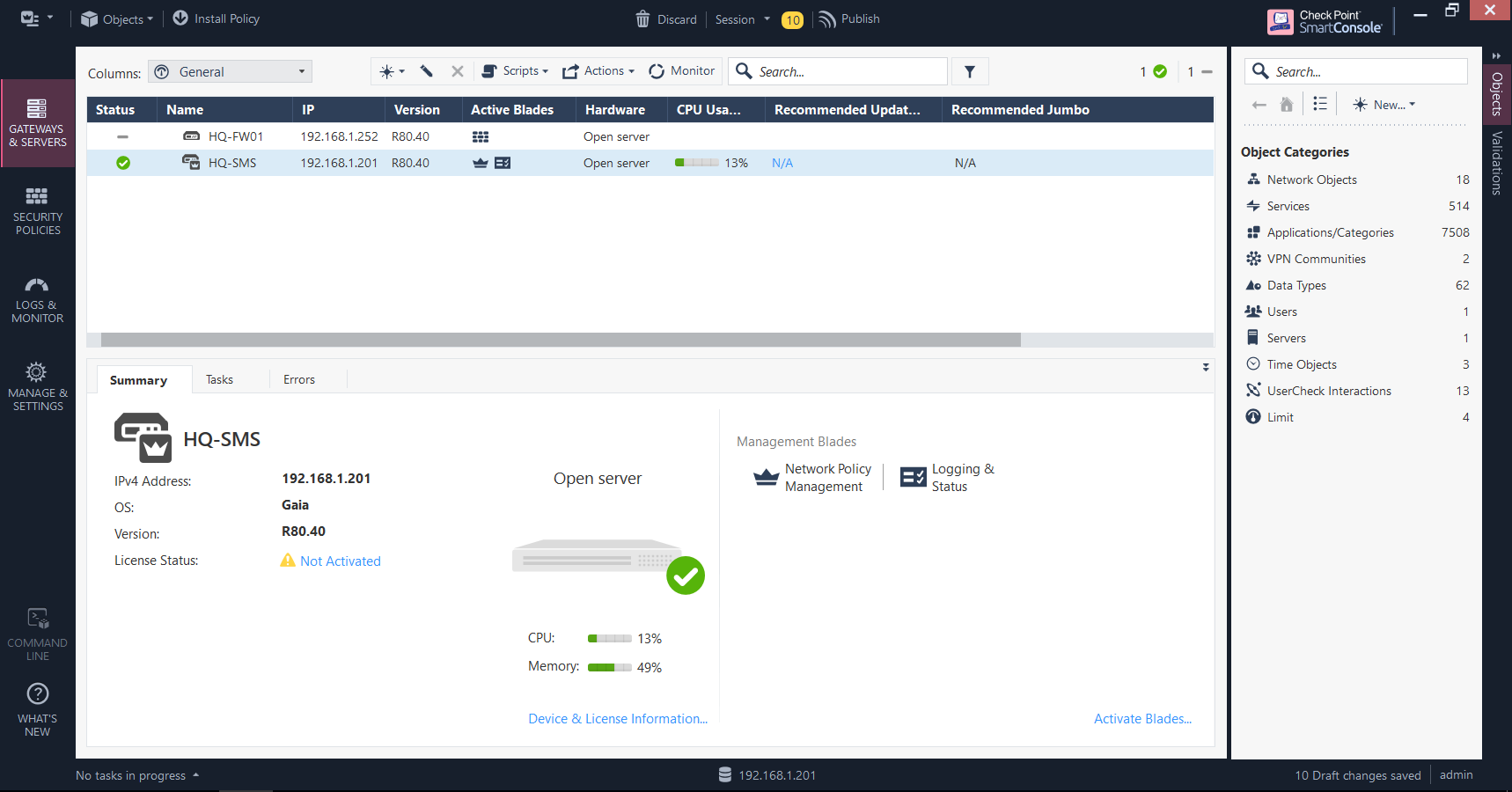
Gateways & Servers
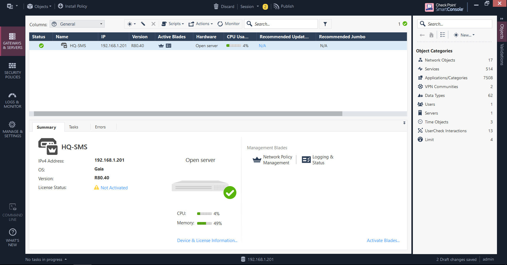
This is where you add and manage your gateways, view their respective statuses, and activate/configure software blades (features). You can use the search bar at the top to search for a particular gateway if you don’t fancy scrolling up and down the list for it. The bottom half of this screen provides information on a selected gateway, such as the version of Gaia it’s currently running, the current CPU/memory utilisation and which blades are enabled.
Security Policies
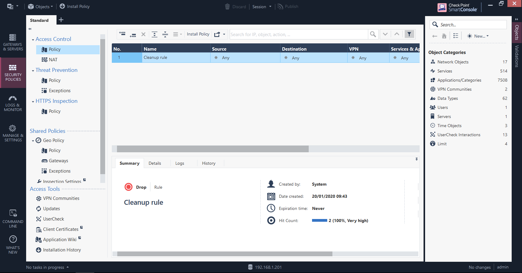
Perhaps the heart of the security policy, this is where the rule base is assembled. Here you can view all of your current rules and corresponding details (such as when they were created, how many times they have been matched, and when they were last hit), view NAT rules and - if the blade is enabled - threat prevention policies. This will be explored in an upcoming post as part of a later objective.
Logs & Monitor
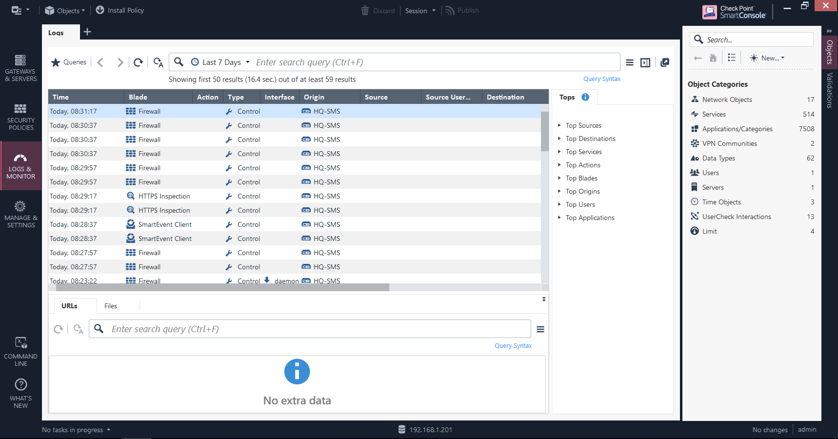
This section is where you can search through logs using pre-defined or custom-made queries and export these for offline investigation, monitor your gateways, analyse events - real-time or otherwise - in a variety of views, and generate and schedule reports.
Manage & Settings
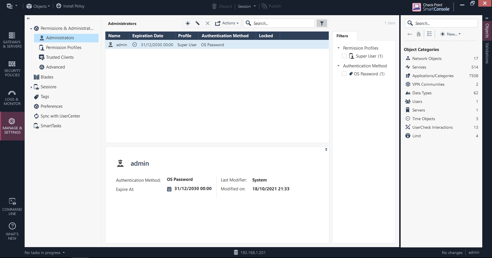
The housekeeping section, for want of a better way of describing it. New administrators and users can be added and assigned roles here, software blades are managed globally, user sessions and revisions to the rule base can be viewed, and other general tasks and preferences can be performed.
Adding Your Gateway
It wouldn’t make sense to have our appliances ready to go, only to not use SmartConsole to manage them all centrally - especially since this is the only means of implementing your security policy. Here, we will walk through how to add your first gateway.
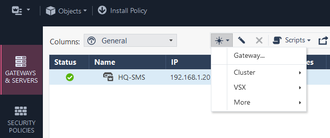
First, click on the symbol that looks like a starburst and select Gateway:
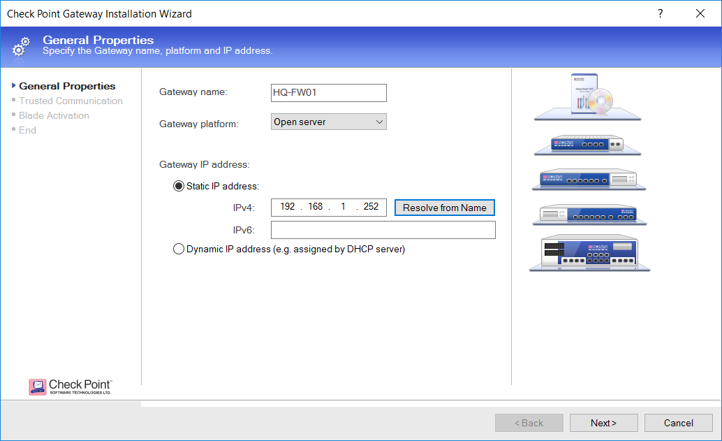
Specify the hostname and platform for the gateway. You can either manually enter the IP address that you’ve chosen or - if you have a Domain Controller as well, and an A record created for your VMs in DNS - click Resolve from Name:
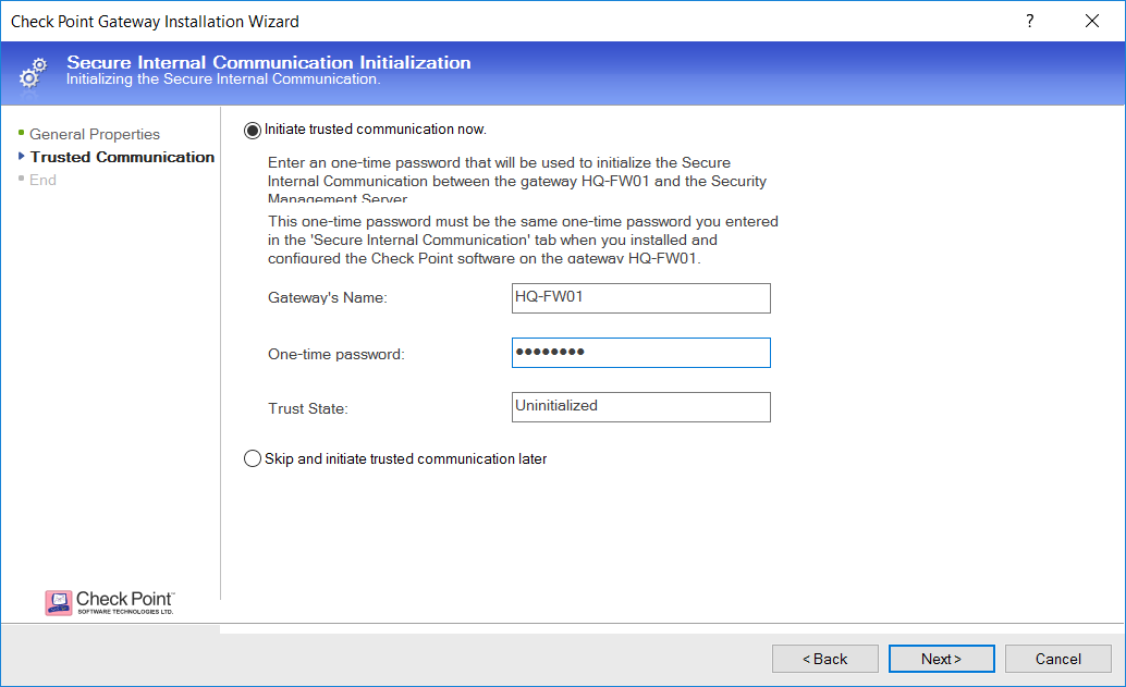
The next step is to set up SIC between the gateway and the SMS. Enter the hostname once more, then the one-time password you set up during the installation stage:
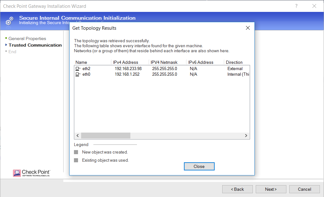
If successful, the gateway’s configured interfaces and their location relative to the topology (i.e. internal or external) - click Close:
Once satisfied with the configuration, click Finish:
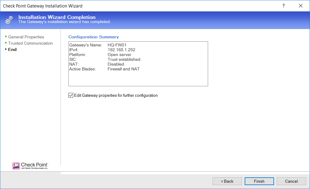
The new gateway is now available and ready:
Resetting SIC
In the last post I explained what SIC is, what it’s used for and how it works. As counter-productive as it may sound given its importance to the communication between appliances, there are certain reasons why SIC might need to be reset in the real world: for example, traffic between the gateway/s and the SMS on one or more of the TCP ports associated with SIC is no longer being permitted, the trust has been somehow compromised, or something else has gone wrong along the way. Here, I will demonstrate how this is done.
Firstly, connect to the SMS via SmartConsole. Making sure you’re in the Gateways & Servers view, double-click on your gateway to open its properties:
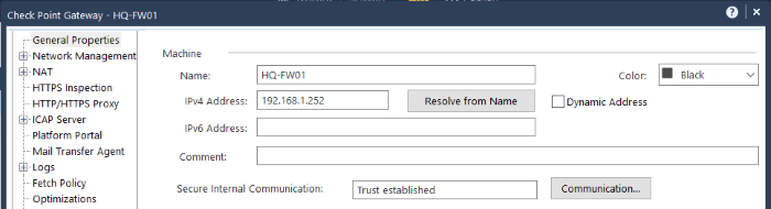
You can see under Secure Internal Communication that the current status is “Trust established”. Click the Communication button, followed by Test SIC Status in the subsequent window to show more information:
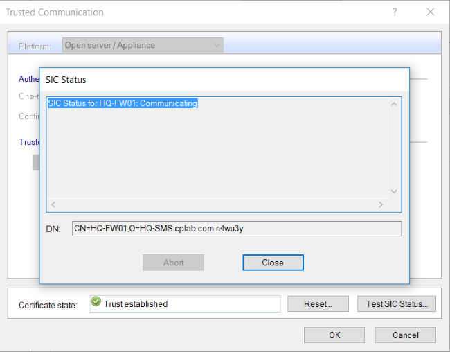
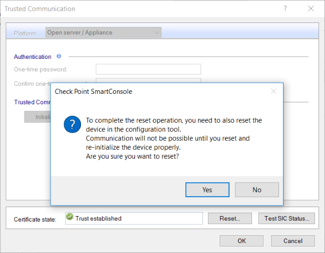
The gateway and SMS are communicating, trust is established, and everything is looking good - however, we’re about to change that. Close the window and click the Reset button, answering Yes to the pop-up question ensuring that you want to do so…
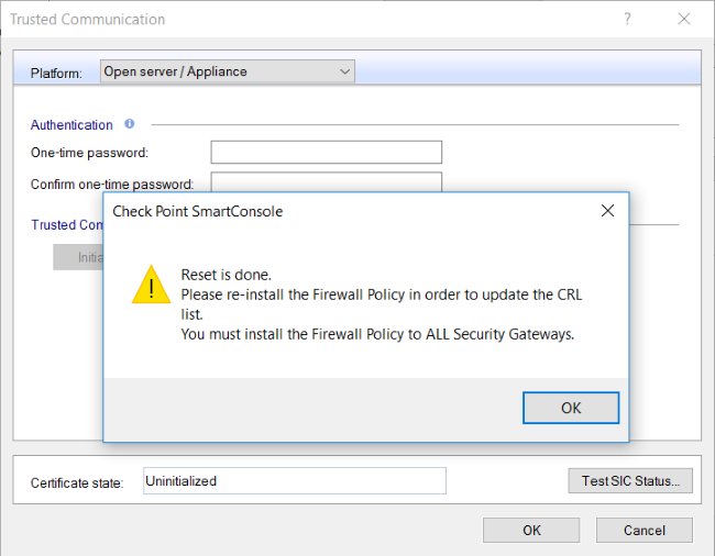
… then click OK on the next pop-up:
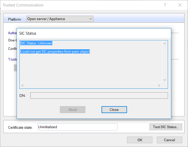
Click Test SIC Status again, and we can now confirm that SIC is no longer working:
As highlighted in the first pop-up message, we also need to do a little bit of work on the CLI. Connect to the gateway via SSH and run cpconfig, selecting option 5 for SIC when prompted and pressing Enter:
HQ-FW01> cpconfig
This program will let you re-configure
your Check Point products configuration.


Configuration Options:
----------------------
(1)  Licenses and contracts
(2)  SNMP Extension
(3)  PKCS#11 Token
(4)  Random Pool
(5)  Secure Internal Communication
(6)  Enable cluster membership for this gateway
(7)  Check Point CoreXL
(8)  Automatic start of Check Point Products

(9) Exit

Enter your choice (1-9) :5
Answer ‘y’ and press Enter when asked to re-initialise the communication:
Configuring Secure Internal Communication...
============================================
The Secure Internal Communication is used for authentication between
Check Point components

Trust State: Trust established

 Would you like re-initialize communication? (y/n) [n] ? y
You’ll be asked again, just to be sure - answer ‘y’ again and enter the one-time password twice:
Note: The Secure Internal Communication will be reset now,
and all Check Point Services will be stopped (cpstop).
No communication will be possible until you reset and
re-initialize the communication properly!
Are you sure? (y/n) [n] ? y
Enter Activation Key:
Retype Activation Key:
Once the key has been successfully re-initialised, enter option 9 to exit and press Enter:
initial_module:
Compiled OK.
initial_module:
Compiled OK.

Hardening OS Security: Initial policy will be applied
until the first policy is installed


The Secure Internal Communication was successfully initialized


Configuration Options:
----------------------
(1)  Licenses and contracts
(2)  SNMP Extension
(3)  PKCS#11 Token
(4)  Random Pool
(5)  Secure Internal Communication
(6)  Enable cluster membership for this gateway
(7)  Check Point CoreXL
(8)  Automatic start of Check Point Products

(9) Exit

Enter your choice (1-9) :9
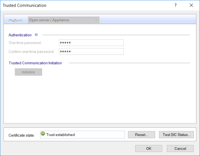
This will restart all the system processes. After a few minutes, once this is done, go back to SmartConsole, type in the one-time password you specified and click Initialize…
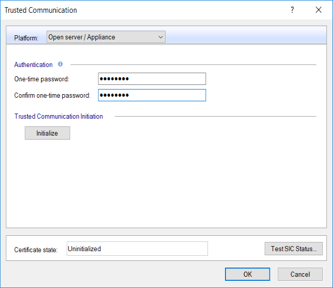
…and we can see that trust is now re-established:
Click OK, close the subsqeuent Topology Results window, and then OK to close the gateway properties window:
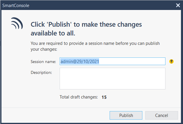
For the last step, publish any outstanding changes…
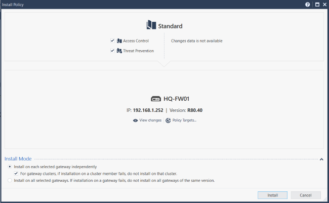
…then install the policy:
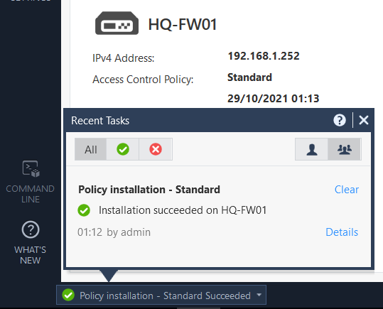
All being well, this should be successful:
Conclusion
That concludes the Introduction to Check Point Technologies objective, and we covered a fair bit of ground over these last couple of posts. This might seem like a lot to take in at once, so - like anything else - don’t expect it all to stick immediately. Just make sure you get your practice in and lab as much as you can - repetition is the mother of all learning, after all.
Next up is the second obejctive, Security Policy Management, where we will look into the different elements of a security policy - from rules to objects - and how these dictate traffic inspection. In the meantime, thank you once again for reading.